Differential Pressure in Compressed Air Filters at Non-Standard Conditions
Pressure drop, differential pressure, delta P or pressure loss in a compressed air system are all terms that refer to the difference between the pressure at the compressor outlet and the pressure at the compressed air point of use. The most common unit of measure for pressure drop in North America is “PSID”.
What Causes Pressure Drop?
Pressure drop is due to resistance to flow or friction losses encountered by the compressed air as it flows through piping, valves, fittings and air treatment components. System leaks must be avoided because they cause flow loss resulting in pressure loss. The total system pressure drop is the sum of the losses due to each component and any leaks in the system.
When total system pressure drop hinders point of use operations and requires increasing the compressor's output, the increased demand is termed “artificial demand”. The increase in drive energy of a typical compressor to overcome artificial demand is a little over 1% per 2 PSID. So a goal of air system designers is to balance system cost with pressure drop and operating efficiency.
The optimal system design will keep artificial demand low, thereby keeping energy consumption low. Any short term peak demands can be adsorbed via air receivers. It is also important to consider the effects of typical operating demands and diminishing returns when selecting components. In other words do not select a component that is either too small or too large.
Sometimes the designer needs to select a component that will have a pressure drop that increases with usage. Sometimes changing operating conditions are different than the manufactures published operating conditions for a component and corrections are required. Compressed air filters are the prime example. The pressure drop through filters varies with actual conditions but increases over time as contaminants accumulate.
Types of Compressed Air Filters
Compressed air filters fall into two categories.
Coalescing Filter
The coalescing filter is used to protect drying equipment from harmful water and oil aerosols downstream of the compressor, after-cooler, and bulk moisture separator. Most manufacturers publish a “clean and dry” pressure drop figure.
This clean and dry figure is usually based on a nominal flow rate, 100 PSIG operating pressure, and 100F operating temperature. Once the coalescing filter element is in operation and gets wet, there will be an additional 1.5 to 2.5 PSID, depending on the application and type of filter element. Coalescing filters are typically effective up to 6 - 9 PSID. Of course, elements can be replaced at a lower PSID if the operator wants to minimize pressure differential.
Particulate Filter
The second type of filter removes dust from desiccants, pipe scale or other solid contaminants in the air system. Particulate filters are normally installed downstream of the compressed air dryer and/or at the point of use. Particulate filters are also most useful up to 6 - 9 PSID. Again the elements can be changed out earlier to reduce pressure differential. Remember pressure differential costs you money indirectly by forcing the compressor to work harder.
When filters are selected it is important to consider both the initial pressure drop, the recommended end of life pressure drop and any changes in pressure drop due to variances in flow and operating conditions.
Most manufacturers publish the known pressure drop at a flow rated in SCFM at operating conditions of 100°F and 100PSIG. Some manufacturers publish two figures. One for the pressure drop caused by the element itself and another for the pressure differential caused by turbulence through the filter housing itself. In these cases the two numbers must be combined to know the total differential pressure through the filter.T
The pressure drop of compressed air through fixed volume devices is proportional to the square of its velocity. Actual flow of compressible fluid also varies with changing pressures and temperatures. Combining these into an equation yields an approximate correction for differential pressure loss through a filter or other component at a flow, temperature or pressure other than the manufacturer's rated condition: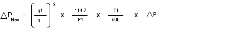
This formula calculates the pressure drop at variable conditions, through a component whose pressure drop is known at a given flow and at 100 psig & 100 ºF.
Where:
P = published pressure drop (psid)
q = rated published flow (SCFM) at 100 psig & 100 ºF with known published pressure drop
q1 = new actual flow (SCFM)
P1 = actual operating pressure absolute (psia = psig + 14.7)
T1 = actual absolute operating temperature, Kelvin (°K = °F + 459.67) often rounded to 460
Example 1: A coalescing filter element designed to flow 600 SCFM of air at 100 PSIG @ 100 ºF has a known pressure drop of 0.3 PSI clean and dry. The pressure drop through the housing is 0.2 PSI. The system is a non-lubricated compressor and the wetting of the element adds 1.5 PSID. What will the wetted pressure drop be through the filter if 520 SCFM of compressed air at 120 psig & 95 ºF flows through it?
120psig + 14.7 = 134.7 PSIA, 95°F + 460 = 555 °K, 0.3 + 0.2 + 1.5 = 2.0 psid
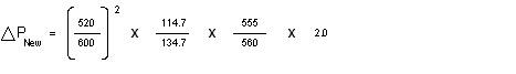
Answer: = 1.25 PSID
Example 2: A downstream particulate filter element designed to flow 600 SCFM of air at 100 PSIG and 100 ºF has a known pressure drop of 0.5 PSI, clean and dry. The pressure drop through the housing is 0.2 PSI. What will the clean dry pressure drop be through the filter if 510 SCFM of compressed air at 110 psig & 90 ºF flows through it?
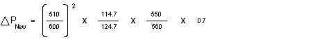
Answer: = 0.46 PSID
Being able to calculate pressure drops at non-standard conditions is a valuable skill for any air system designer or vendor of compressed air treatment equipment. In the real world, air systems rarely operate exactly at the manufacturer's nominal ratings.
If you have questions or need support with an application, Email Us today!